Author Archive norbertk

List of TTL IC’s

Part numberDescription
7400quad 2-input NAND gate
7401quad 2-input NAND gate with open collector outputs
7402quad 2-input NOR gate
7403quad 2-input NAND gate with open collector outputs
7404hex inverter
7405hex inverter with open collector outputs
7406hex inverter buffer/driver with 30 V open collector outputs
7407hex buffer/driver with 30 V open collector outputs
7408quad 2-input AND gate
7409quad 2-input AND gate with open collector outputs
7410triple 3-input NAND gate
7411triple 3-input AND gate
7412triple 3-input NAND gate with open collector outputs
7413dual Schmitt trigger 4-input NAND gate
7414hex Schmitt trigger inverter
7415triple 3-input AND gate with open collector outputs
7416hex inverter buffer/driver with 15 V open collector outputs
7417hex buffer/driver with 15 V open collector outputs
7418dual 4-input NAND gate with Schmitt trigger inputs
7419hex Schmitt trigger inverter
7420dual 4-input NAND gate
7421dual 4-input AND gate
7422dual 4-input NAND gate with open collector outputs
7423expandable dual 4-input NOR gate with strobe
7424quad 2-input NAND gate gates with schmitt-trigger line-receiver inputs.
7425dual 4-input NOR gate with strobe
7426quad 2-input NAND gate with 15 V open collector outputs
7427triple 3-input NOR gate
7428quad 2-input NOR buffer
74308-input NAND gate
7431hex delay elements
7432quad 2-input OR gate
7433quad 2-input NOR buffer with open collector outputs
7434hex noninverters
7435hex noninverters with open-collector outputs
7436quad 2-input NOR gate (different pinout than 7402)
7437quad 2-input NAND buffer
7438quad 2-input NAND buffer with open collector outputs
7439quad 2-input NAND buffer with open collector outputs, input and output terminals flipped, otherwise functionally identical to 7438
7440dual 4-input NAND buffer
7441BCD to decimal decoder/Nixie tube driver
7442BCD to decimal decoder
7443excess-3 to decimal decoder
7444excess-3-Gray code to decimal decoder
7445BCD to decimal decoder/driver
7446BCD to seven-segment display decoder/driver with 30 V open collector outputs
7447BCD to 7-segment decoder/driver with 15 V open collector outputs
7448BCD to 7-segment decoder/driver with Internal Pullups
7449BCD to 7-segment decoder/driver with open collector outputs
7450dual 2-wide 2-input AND-OR-invert gate (one gate expandable)
7451dual 2-wide 2-input AND-OR-invert gate
7452expandable 4-wide 2-input AND-OR gate
7453expandable 4-wide 2-input AND-OR-invert gate
74543-2-2-3-input AND-OR-invert gate
74552-wide 4-input AND-OR-invert Gate (74H version is expandable)
745650:1 frequency divider
745760:1 frequency divider
74582-input & 3-input AND-OR Gate
74592-input & 3-input AND-OR-invert Gate
7460dual 4-input expander
7461triple 3-input expander
74623-2-2-3-input AND-OR expander
7463hex current sensing interface gates
74644-2-3-2-input AND-OR-invert gate
74654-2-3-2 input AND-OR-invert gate with open collector output
7468dual 4 bit decade counters
7469dual 4 bit binary counters
7470AND-gated positive edge triggered J-K flip-flop with preset and clear
7471AND-or-gated J-K master-slave flip-flop with preset
7472AND gated J-K master-slave flip-flop with preset and clear
7473dual J-K flip-flop with clear
7474dual D positive edge triggered flip-flop with preset and clear
74754-bit bistable latch
7476dual J-K flip-flop with preset and clear
74774-bit bistable latch
7478dual positive pulse triggered J-K flip-flop with preset, common clock, and common clear
7479dual D flip-flop
7480gated full adder
748116-bit random access memory
74822-bit binary full adder
74834-bit binary full adder
748416-bit random access memory
74854-bit magnitude comparator
7486quad 2-input XOR gate
74874-bit true/complement/zero/one element
7488256-bit read-only memory
748964-bit random access memory
7490decade counter (separate divide-by-2 and divide-by-5 sections)
74918-bit shift register, serial In, serial out, gated input
7492divide-by-12 counter (separate divide-by-2 and divide-by-6 sections)
74934-bit binary counter (separate divide-by-2 and divide-by-8 sections)
74944-bit shift register, dual asynchronous presets
74954-bit shift register, parallel In, parallel out, serial input
74965-bit parallel-In/parallel-out shift register, asynchronous preset
7497synchronous 6-bit binary rate multiplier
74984-bit data selector/storage register
74994-bit bidirectional universal shift register
74100dual 4-bit bistable latch
74101AND-OR-gated J-K negative-edge-triggered flip-flop with preset
74102AND-gated J-K negative-edge-triggered flip-flop with preset and clear
74103dual J-K negative-edge-triggered flip-flop with clear
74104J-K master-slave flip-flop
74105J-K master-slave flip-flop
74106dual J-K negative-edge-triggered flip-flop with preset and clear
74107dual J-K flip-flop with clear
74108dual J-K negative-edge-triggered flip-flop with preset, common clear, and common clock
74109dual J-Not-K positive-edge-triggered flip-flop with clear and preset
74110AND-gated J-K master-slave flip-flop with data lockout
74111dual J-K master-slave flip-flop with data lockout
74112dual J-K negative-edge-triggered flip-flop with clear and preset
74113dual J-K negative-edge-triggered flip-flop with preset
74114dual J-K negative-edge-triggered flip-flop with preset, common clock and clear
74116dual 4-bit latch with clear
74118hex set/reset latch
74119hex set/reset latch
74120dual pulse synchronizer/drivers
74121monostable multivibrator
74122retriggerable monostable multivibrator with clear
74123dual retriggerable monostable multivibrator with clear
74124dual voltage-controlled oscillator
74125quad bus buffer with three-state outputs, negative enable
74126quad bus buffer with three-state outputs, positive enable
74128quad 2-input NOR Line driver
74130quad 2-input AND gate buffer with 30 V open collector outputs
74131quad 2-input AND gate buffer with 15 V open collector outputs
74132quad 2-input NAND schmitt trigger
7413313-input NAND gate
7413412-input NAND gate with three-state output
74135quad exclusive-or/NOR gate
74136quad 2-input XOR gate with open collector outputs
741373 to 8-line decoder/demultiplexer with address latch
741383 to 8-line decoder/demultiplexer
74139dual 2 to 4-line decoder/demultiplexer
74140dual 4-input NAND line driver
74141BCD to decimal decoder/driver for cold-cathode indicator/Nixie tube
74142decade counter/latch/decoder/driver for Nixie tubes
74143decade counter/latch/decoder/7-segment driver, 15 ma constant current
74144decade counter/latch/decoder/7-segment driver, 15 V open collector outputs
74145BCD to decimal decoder/driver
7414710-line to 4-line priority encoder
741488-line to 3-line priority encoder
7415016-line to 1-line data selector/multiplexer
741518-line to 1-line data selector/multiplexer
741528-line to 1-line data selector/multiplexer
74153dual 4-line to 1-line data selector/multiplexer
741544-line to 16-line decoder/demultiplexer
74155dual 2-line to 4-line decoder/demultiplexer
74156dual 2-line to 4-line decoder/demultiplexer with open collector outputs
74157quad 2-line to 1-line data selector/multiplexer, noninverting
74158quad 2-line to 1-line data selector/multiplexer, inverting
741594-line to 16-line decoder/demultiplexer with open collector outputs
74160synchronous 4-bit decade counter with asynchronous clear
74161synchronous 4-bit binary counter with asynchronous clear
74162synchronous 4-bit decade counter with synchronous clear
74163synchronous 4-bit binary counter with synchronous clear
741648-bit parallel-out serial shift register with asynchronous clear
741658-bit serial shift register, parallel Load, complementary outputs
74166parallel-Load 8-bit shift register
74167synchronous decade rate multiplier
74168synchronous 4-bit up/down decade counter
74169synchronous 4-bit up/down binary counter
741704 by 4 register file with open collector outputs
74171quad D-type flip-flops with clear
7417216-bit multiple port register file with three-state outputs
74173quad d flip-flop with three-state outputs
74174hex d flip-flop with common clear
74175quad d edge-triggered flip-flop with complementary outputs and asynchronous clear
74176presettable decade (bi-quinary) counter/latch
74177presettable binary counter/latch
741784-bit parallel-access shift register
741794-bit parallel-access shift register with asynchronous clear and complementary Qd outputs
741809-bit odd/even parity bit generator and checker
741814-bit arithmetic logic unit and function generator
74182lookahead carry generator
74183dual carry-save full adder
74184BCD to binary converter
741856-bit binary to BCD converter
74186512-bit (64×8) read-only memory with open collector outputs
741871024-bit (256×4) read only memory with open collector outputs
74188256-bit (32×8) programmable read-only memory with open collector outputs
7418964-bit (16×4) RAM with inverting three-state outputs
74190synchronous up/down decade counter
74191synchronous up/down binary counter
74192synchronous up/down decade counter with clear
74193synchronous up/down 4-bit binary counter with clear
741944-bit bidirectional universal shift register
741954-bit parallel-access shift register
74196presettable decade counter/latch
74197presettable binary counter/latch
741988-bit bidirectional universal shift register
741998-bit bidirectional universal shift register with J-Not-K serial inputs
74200256-bit ram with three-state outputs
74201256-bit (256×1) ram with three-state outputs
74206256-bit ram with open collector outputs
742091024-bit (1024×1) ram with three-state output
74210octal buffer
7421964-bit (16×4) RAM with noninverting three-state outputs
74221dual monostable multivibrator with schmitt trigger input
7422216 by 4 synchronous FIFO memory with three-state outputs
7422416 by 4 synchronous FIFO memory with three-state outputs
74225asynchronous 16×5 FIFO memory
742264-bit parallel latched bus transceiver with three-state outputs
7422764-bit fifo memories 16×4
7422864-bit fifo memories 16×4 open-collector outputs
74230octal buffer/driver with three-state outputs, true and complementary inputs
74231octal buffer and line driver with three-state outputs, G and /G complementary inputs
74232quad NOR Schmitt trigger
742373-of-8 decoder/demultiplexer with address latch, active high outputs
742383-of-8 decoder/demultiplexer, active high outputs
74239dual 2-of-4 decoder/demultiplexer, active high outputs
74240octal buffer with Inverted three-state outputs
74241octal buffer with noninverted three-state outputs
74242quad bus transceiver with Inverted three-state outputs
74243quad bus transceiver with noninverted three-state outputs
74244octal buffer with noninverted three-state outputs
74245octal bus transceiver with noninverted three-state outputs
74246BCD to 7-segment decoder/driver with 30 V open collector outputs
74247BCD to 7-segment decoder/driver with 15 V open collector outputs
74248BCD to 7-segment decoder/driver with Internal Pull-up outputs
74249BCD to 7-segment decoder/driver with open collector outputs
742501 of 16 data selectors/multiplexers
742518-line to 1-line data selector/multiplexer with complementary three-state outputs
74253dual 4-line to 1-line data selector/multiplexer with three-state outputs
74255dual 4-bit addressable latch
74256dual 4-bit addressable latch
74257quad 2-line to 1-line data selector/multiplexer with noninverted three-state outputs
74258quad 2-line to 1-line data selector/multiplexer with Inverted three-state outputs
742598-bit addressable latch
74260dual 5-input NOR gate
742612-bit by 4-bit parallel binary multiplier
74264look ahead carry generator
74265quad complementary output elements
74266quad 2-input XNOR gate with open collector outputs
74268hex d-type latches three-state outputs, common output control, common enable
742702048-bit (512×4) read only memory with open collector outputs
742712048-bit (256×8) read only memory with open collector outputs
742738-bit register with reset
742744-bit by 4-bit binary multiplier
742757-bit slice Wallace tree
74276quad J-Not-K edge-triggered Flip-Flops with separate clocks, common preset and clear
742784-bit cascadeable priority registers with latched data inputs
74279quad set-reset latch
742809-bit odd/even Parity bit Generator/checker
742814-bit parallel binary accumulator
74282look-ahead carry generator with selectable carry inputs
742834-bit binary Full adder
742844-bit by 4-bit parallel binary multiplier (low order 4 bits of product)
742854-bit by 4-bit parallel binary multiplier (high order 4 bits of product)
742869-bit parity generator/checker with bus driver parity I/O port
742871024-bit (256×4) programmable read-only memory with three-state outputs
74288256-bit (32×8) programmable read-only memory with three-state outputs
7428964-bit (16×4) RAM with open collector outputs
74290decade counter (separate divide-by-2 and divide-by-5 sections)
742914-bit universal shift register, binary up/down counter, synchronous
74292programmable frequency divider/digital timer
742934-bit binary counter (separate divide-by-2 and divide-by-8 sections)
74294programmable frequency divider/digital timer
742954-bit bidirectional register with three-state outputs
74297digital phase-locked-loop filter
74298quad 2-input multiplexer with storage
742998-bit bidirectional universal shift/storage register with three-state outputs
74301256-bit (256×1) random access memory with open collector output
743091024-bit (1024×1) random access memory with open collector output
74310octal buffer with Schmitt trigger inputs
743141024-bit random access memory
7431964-bit random access memories 16×4 open collector outputs
74320crystal controlled oscillator
74321crystal-controlled oscillators with F/2 and F/4 count-down outputs
743228-bit shift register with sign extend, three-state outputs
743238-bit bidirectional universal shift/storage register with three-state outputs
74324voltage controlled oscillator (or crystal controlled)
74340octal buffer with Schmitt trigger inputs and three-state inverted outputs
74341octal buffer with Schmitt trigger inputs and three-state noninverted outputs
74344octal buffer with Schmitt trigger inputs and three-state noninverted outputs
74347bcd to seven segment decoders/drivers open collector outputs, low voltage version of 7447
743488 to 3-line priority encoder with three-state outputs
743504-bit shifter with three-state outputs
74351dual 8-line to 1-line data selectors/multiplexers with three-state outputs and 4 common data inputs
74352dual 4-line to 1-line data selectors/multiplexers with inverting outputs
74353dual 4-line to 1-line data selectors/multiplexers with inverting three-state outputs
743548 to 1-line data selector/multiplexer with transparent latch, three-state outputs
743558-line to 1-line data selector/multiplexer with transparent registers, open-collector outputs
743568 to 1-line data selector/multiplexer with edge-triggered register, three-state outputs
743578-line to 1-line data selectors/multiplexers/edge-triggered registers, open-collector outputs
74361bubble memory function timing generator
74362four-phase clock generator/driver
74363octal three-state D-latches
74365hex buffer with noninverted three-state outputs
74366hex buffer with Inverted three-state outputs
74367hex buffer with noninverted three-state outputs
74368hex buffer with Inverted three-state outputs
743702048-bit (512×4) read-only memory with three-state outputs
743712048-bit (256×8) read-only memory with three-state outputs
74373octal transparent latch with three-state outputs
74374octal register with three-state outputs
74375quad bistable latch
74376quad J-Not-K flip-flop with common clock and common clear
743778-bit register with clock enable
743786-bit register with clock enable
743794-bit register with clock enable and complementary outputs
743808-bit multifunction register
743814-bit arithmetic logic unit/function generator with generate and propagate outputs
743824-bit arithmetic logic unit/function generator with ripple carry and overflow outputs
743848-bit by 1-bit two’s complement multipliers
74385quad 4-bit adder/subtractor
74386quad 2-input XOR gate
743871024-bit (256×4) programmable read-only memory with open collector outputs
743884-bit register with standard and three-state outputs
74390dual 4-bit decade counter
74393dual 4-bit binary counter
743954-bit universal shift register with three-state outputs
74396octal storage registers, parallel access
74398quad 2-input multiplexers with storage and complementary outputs
74399quad 2-input multiplexer with storage
744051 to 8 decoder, equivalent to Intel 8205, only found as UCY74S405 so might be non-TI number
744088-bit parity tree
74412multi-mode buffered 8-bit latches with three-state outputs and clear
74422re-triggerable mono-stable multivibrators, two inputs
74423dual retriggerable monostable multivibrator
74424two-phase clock generator/driver
74425quad gates with three-state outputs and active low enables
74426quad gates with three-state outputs and active high enables
74428system controller for 8080a
74436line driver/memory driver circuits – mos memory interface, damping output resistor
74437line driver/memory driver circuits – mos memory interface
74438system controller for 8080a
74440quad tridirectional bus transceiver with noninverted open collector outputs
74441quad tridirectional bus transceiver with Inverted open collector outputs
74442quad tridirectional bus transceiver with noninverted three-state outputs
74443quad tridirectional bus transceiver with Inverted three-state outputs
74444quad tridirectional bus transceiver with Inverted and noninverted three-state outputs
74445bcd-to-decimal decoders/drivers
74446quad bus transceivers with direction controls
74447bcd-to-seven-segment decoders/drivers, low voltage version of 74247
74448quad tridirectional bus transceiver with Inverted and noninverted open collector outputs
74449quad bus transceivers with direction controls, true outputs
7445016-to-1 multiplexer with complementary outputs
74451dual 8-to-1 multiplexer
74452dual decade counter, synchronous
74453dual binary counter, synchronous
74453quad 4-to-1 multiplexer
74454dual decade up/down counter, synchronous, preset input
74455dual binary up/down counter, synchronous, preset input
74456NBCD (Natural binary coded decimal) adder
74460bus transfer switch
744618-bit presettable binary counter with three-state outputs
74462fiber-optic link transmitter
74463fiber-optic link receiver
74465octal buffer with three-state true outputs
74466octal buffers with three-state inverted outputs
74467octal buffers with three-state true outputs
74468octal buffers with three-state inverted outputs
744702048-bit (256×8) programmable read-only memory with open collector outputs
744712048-bit (256×8) programmable read-only memory with three-state outputs
74472programmable read-only memory with open collector outputs
74473programmable read-only memory with three-state outputs
74474programmable read-only memory with open collector outputs
74475programmable read-only memory with three-state outputs
744814-bit slice cascadable processor elements
744824-bit slice expandable control elements
74484BCD-to-binary converter
74485binary-to-BCD converter
74490dual decade counter
7449110-bit binary up/down counter with limited preset and three-state outputs
744988-bit bidirectional shift register with parallel inputs and three-state outputs
745088-bit multiplier/divider
745188-bit comparator with open collector output, input pull-up resistor
745198-bit comparator with open collector output
745208-bit comparator with inverted totem-pole output, input pull-up resistor
745218-bit comparator with inverted totem-pole output
745228-bit comparator with inverted open-collector output, input pull-up resistor
74526fuse programmable identity comparator, 16 bit
74527fuse programmable identity comparator, 8 bit + 4 bit conventional Identity comparator
74528fuse programmable Identity comparator, 12 bit
74531octal transparent latch with 32 ma three-state outputs
74532octal register with 32 ma three-state outputs
74533octal transparent latch with inverting three-state outputs
74534octal register with inverting three-state outputs
74535octal transparent latch with inverting three-state outputs
74536octal register with inverting 32 ma three-state outputs
74537BCD to decimal decoder with three-state outputs
745381 of 8 decoder with three-state outputs
74539dual 1 of 4 decoder with three-state outputs
74540inverting octal buffer with three-state outputs
74541non-inverting octal buffer with three-state outputs
74544non-inverting octal registered transceiver with three-state outputs
745588-bit by 8-bit multiplier with three-state outputs
745604-bit decade counter with three-state outputs
745614-bit binary counter with three-state outputs
745638-bit d-type transparent latch with inverting three-state outputs
745648-bit d-type edge-triggered register with inverting three-state outputs
74568decade up/down counter with three-state outputs
74569binary up/down counter with three-state outputs
74573octal D-type transparent latch with three-state outputs
74574octal D-type edge-triggered flip-flop with three-state outputs
74575octal D-type flip-flop with synchronous clear, three-state outputs
74576octal D-type flip-flop with inverting three-state outputs
74577octal D-type flip-flop with synchronous clear, inverting three-state outputs
74580octal transceiver/latch with inverting three-state outputs
745898-bit shift register with input latch, three-state outputs
745908-bit binary counter with output registers and three-state outputs
745918-bit binary counters with output registers, open-collector outputs
745928-bit binary counter with input registers
745938-bit binary counter with input registers and three-state outputs
745948-bit shift registers with output latches
745958-bit shift registers with output latches, three-state parallel outputs
745968-bit shift registers with output latches, open-collector parallel outputs
745978-bit shift registers with input latches
745988-bit shift register with input latches
745998-bit shift registers with output latches, open-collector outputs
74600dynamic memory refresh controller, transparent and burst modes, for 4K or 16K drams
74601dynamic memory refresh controller, transparent and burst modes, for 64K drams
74602dynamic memory refresh controller, cycle steal and burst modes, for 4K or 16K drams
74603dynamic memory refresh controller, cycle steal and burst modes, for 64K drams
74604octal 2-input multiplexer with latch, high-speed, with three-state outputs
74605latch, high-speed, with open collector outputs
74606octal 2-input multiplexer with latch, glitch-free, with three-state outputs
74607octal 2-input multiplexer with latch, glitch-free, with open collector outputs
74608memory cycle controller
74610memory mapper, latched, three-state outputs
74611memory mapper, latched, open collector outputs
74612memory mapper, three-state outputs
74613memory mapper, open collector outputs
74618Schmitt-trigger positive-nand gates with totem-pole outputs
74619Schmitt-trigger inverters with totem-pole outputs
74620octal bus transceiver, inverting, three-state outputs
74621octal bus transceiver, noninverting, open collector outputs
74622octal bus transceiver, inverting, open collector outputs
74623octal bus transceiver, noninverting, three-state outputs
74624voltage-controlled oscillator with enable control, range control, two-phase outputs
74625dual voltage-controlled oscillator with two-phase outputs
74626dual voltage-controlled oscillator with enable control, two-phase outputs
74627dual voltage-controlled oscillator
74628voltage-controlled oscillator with enable control, range control, external temperature compensation, and two-phase outputs
74629dual voltage-controlled oscillator with enable control, range control
7463016-bit error detection and correction (EDAC) with three-state outputs
7463116-bit error detection and correction with open collector outputs
7463232-bit parallel error detection and correction, three-state outputs, byte-write
7463332-bit parallel error detection and correction, open-collector outputs, byte-write
7463432-bit parallel error detection and correction, three-state outputs
7463532-bit parallel error detection and correction, open-collector outputs
74638octal bus transceiver with inverting three-state outputs
74639octal bus transceiver with noninverting three-state outputs
74640octal bus transceiver with inverting three-state outputs
74641octal bus transceiver with noninverting open collector outputs
74642octal bus transceiver with inverting open collector outputs
74643octal bus transceiver with mix of inverting and noninverting three-state outputs
74644octal bus transceiver with mix of inverting and noninverting open collector outputs
74645octal bus transceiver
74646octal bus transceiver/latch/multiplexer with noninverting three-state outputs
74647octal bus transceiver/latch/multiplexer with noninverting open collector outputs
74648octal bus transceiver/latch/multiplexer with inverting three-state outputs
74649octal bus transceiver/latch/multiplexer with inverting open collector outputs
74651octal bus transceiver/register with inverting three-state outputs
74652octal bus transceiver/register with noninverting three-state outputs
74653octal bus transceiver/register with inverting three-state and open collector outputs
74654octal bus transceiver/register with noninverting three-state and open collector outputs
74658octal bus transceiver with Parity, inverting
74659octal bus transceiver with Parity, noninverting
74664octal bus transceiver with Parity, inverting
74665octal bus transceiver with Parity, noninverting
74668synchronous 4-bit decade Up/down counter
74669synchronous 4-bit binary Up/down counter
746704 by 4 register File with three-state outputs
746714-bit bidirectional shift register/latch /multiplexer with three-state outputs
746724-bit bidirectional shift register/latch/multiplexer with three-state outputs
7467316-bit serial-in serial-out shift register with output storage registers, three-state outputs
7467416-bit parallel-in serial-out shift register with three-state outputs
7467716-bit address comparator with enable
7467816-bit address comparator with latch
7467912-bit address comparator with latch
7468012-bit address comparator with enable
746814-bit parallel binary accumulator
746828-bit magnitude comparator
746838-bit magnitude comparator with open collector outputs
746848-bit magnitude comparator
746858-bit magnitude comparator with open collector outputs
746868-bit magnitude comparator with enable
746878-bit magnitude comparator with enable
746888-bit equality comparator
746898-bit magnitude comparator with open collector outputs
74690three-state outputs
746914-bit binary counter/latch/multiplexer with asynchronous reset, three-state outputs
746924-bit decimal counter/latch/multiplexer with synchronous reset, three-state outputs
746934-bit binary counter/latch/multiplexer with synchronous reset, three-state outputs
746944-bit decimal counter/latch/multiplexer with synchronous and asynchronous resets, three-state outputs
746954-bit binary counter/latch/multiplexer with synchronous and asynchronous resets, three-state outputs
746964-bit decimal counter/register/multiplexer with asynchronous reset, three-state outputs
746974-bit binary counter/register/multiplexer with asynchronous reset, three-state outputs
746984-bit decimal counter/register/multiplexer with synchronous reset, three-state outputs
746994-bit binary counter/register/multiplexer with synchronous reset, three-state outputs
74716programmable decade counter
74718programmable binary counter
74724voltage controlled multivibrator
74740octal buffer/Line driver, inverting, three-state outputs
74741octal buffer/Line driver, noninverting, three-state outputs, mixed enable polarity
74744octal buffer/Line driver, noninverting, three-state outputs
747488 to 3-line priority encoder
747798-bit bidirectional binary counter (three-state)
74783synchronous address multiplexer
74790error detection and correction (EDAC)
747948-bit register with readback
74795octal buffer with three-state outputs
74796octal buffer with three-state outputs
74797octal buffer with three-state outputs
74798octal buffer with three-state outputs
74804hex 2-input NAND drivers
74805hex 2-input NOR drivers
74808hex 2-input AND drivers
7482210-bit bus interface flipflop with three-state outputs
74832hex 2-input OR drivers
748488 to 3-line priority encoder with three-state outputs
74873octal transparent latch
74874octal d-type flip-flop
74876octal d-type flip-flop with inverting outputs
74878dual 4-bit d-type flip-flop with synchronous clear, noninverting three-state outputs
74879dual 4-bit d-type flip-flop with synchronous clear, inverting three-state outputs
74880octal transparent latchwith inverting outputs
74881arithmetic logic unit
7488232-bit lookahead carry generator
748888-bit slice processor
74901hex inverting TTL buffer
74902hex non-inverting TTL buffer
74903hex inverting CMOS buffer
74904hex non-inverting CMOS buffer
7490512-Bit successive approximation register
74906hex open drain n-channel buffers
74907hex open drain p-channel buffers
74908dual CMOS 30 V relay driver
74909quad voltage comparator
74910256×1 CMOS static RAM
749114 digit expandable display controller
749126 digit BCD display controller and driver
74914hex schmitt trigger with extended input voltage
74915seven segment to BCD decoder
749176 digit Hex display controller and driver
74918dual CMOS 30 V relay driver
74920256×4 CMOS static RAM
74921256×4 CMOS static RAM
7492216-key encoder
7492320-key encoder
749254-digit counter/display driver
749264-digit counter/display driver
749274-digit counter/display driver
749284-digit counter/display driver
749291024×1 CMOS static RAM
749301024×1 CMOS static RAM
74932phase comparator
74933address bus comparator
74934=ADC0829 ADC, see corresponding NSC datasheet
749353.5-digit digital voltmeter (DVM) support chip for multiplexed 7-segment displays
749363.75-digit digital voltmeter (DVM) support chip for multiplexed 7-segment displays
74937=ADC3511 ADC, see corresponding NSC datasheet
74938=ADC3711 ADC, see corresponding NSC datasheet
74941octal bus/line drivers/line receivers
749454 digit up/down counter with decoder and driver
749474 digit up/down counter with decoder and driver
74948=ADC0816 ADC, see corresponding NSC datasheet
74949=ADC0808 ADC, see corresponding NSC datasheet
741005hex inverting buffer with open-collector output
741035hex noninverting buffers with open-collector outputs
742960error detection and correction (EDAC)
742961edac bus buffer, inverting
742962edac bus buffer, noninverting
742968dynamic memory controller
742969memory timing controller for use with EDAC
742970memory timing controller for use without EDAC
744002dual 4-input NOR gate
744015dual 4-bit shift registers
744016quad bilateral switch
7440175-stage ÷10 Johnson counter
74402014-stage binary counter
7440247 stage ripple carry binary counter
744028BCD to decimal decoder
74404012-stage binary ripple counter
744046phase-locked loop and voltage-controlled oscillator
744049hex inverting buffer
744050hex buffer/converter (non-inverting)
744051high-speed CMOS 8-channel analog multiplexer/demultiplexer
744052dual 4-channel analog multiplexer/demultiplexers
744053triple 2-channel analog multiplexer/demultiplexers
744059programmable divide-by-N counter
74406014-stage binary ripple counter with oscillator
744066quad bilateral switches
74406716-channel analog multiplexer/demultiplexer
744075triple 3-input OR gate
7440788-input OR/NOR gate
7440948-bit three-state shift register/latch
744316quad analog switch
7443518-channel analog multiplexer/demultiplexer with latch
744353Triple 2-channel analog multiplexer/demultiplexer with latch
744511BCD to 7-segment decoder
7445144-to-16 line decoder/demultiplexer with input latches
744520dual 4-bit synchronous binary counter
744538dual retriggerable precision monostable multivibrator
747007hex buffer
747266quad 2-input XNOR gate
742984110-bit bus-interface D-type latch with three-state outputs
7440103presettable 8-bit synchronous down counter
74401054-bit by 16-word FIFO register

Single Mode vs. Multimode Fiber Optic Cables

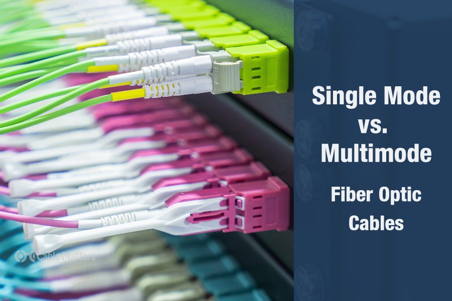
There are two main types of fiber optic cables: single mode and multimode. Although they can do the same job in some instances, the different construction methods make each of them better suited to certain tasks and budgets. That makes picking between single mode and multimode fiber optic cables an important consideration when it comes to setting up your network.

In a nutshell, single mode cables are better for long-distance cable runs and when signal integrity is of paramount importance. They are typically more expensive than multimode cables, though, and there are different types of single and multimode fiber optic cables to consider, making the single mode vs. multimode fiber head-to-head a little more complicated.

To help you decide on the type of cable you need for your project, here’s everything you need to know about single mode and multimode fiber optic cables.

What is Single Mode and What is Multimode?

Single mode and multimode fiber optic cables are two different types of fiber optic cable aimed at different use cases. Single mode cables are typically made with a single strand of glass at their core, leading to a narrower core of the cabling, and more robust signal integrity over greater distances. They can be further divided into OS1 and OS2 cables, which are designed for indoor and outdoor uses, respectively, with OS2 cables offering greater cable lengths and bandwidth.

Multimode cables have multiple glass strands in the core, making them larger and more versatile since they can handle multiple data streams at a time. However, that broader core means there’s more light refraction throughout the cable, weakening the signal faster, and making multimode cables less suitable for longer runs. They too are divided into more cable types: OM1, OM2, OM3OM4, and OM5.

OM1 and OM2 cables are the least expensive but offer the least performance of multimode fiber optic cables. OM3, OM4, and OM5 are progressively more capable, closing the gap between single mode and multimode fiber.

Single Mode vs. Multimode Fiber: Key Differences

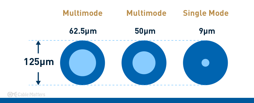
The key physical difference when comparing single mode vs multimode fiber cables is the core. Where single mode cables have a single glass strand at their core, measuring around 9µm, the multiple strands used to craft a multimode cable’s core measure 62.5µm or 50µm. This physical disparity is what leads to the performance and use case differences for each cable type.

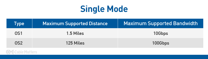
Thanks to the focused signal of single mode cables, they can deliver a signal over multiple miles without the need to repeat or amplify it. OS1 cables can carry a signal up to around a mile and a half, while OS2 cables can reach up to 125 miles. Since they’re designed with outdoor use in mind, and to ensure no problems arise over that expansive length, OS2 single mode fiber cables are also built with a unique spiral core design, with additional semi-rigid tubing around the core that lets the cable flex without putting any tension on the glass fibers at its core.

Single mode cables are typically rated for between 1 and 10 Gigabits per second over these incredible lengths. It’s theoretically possible that they can run at much higher bandwidths, but typical specifications limit them to 10 Gbps at the top end. Single mode cables, specifically OS1 cables, are commonly used in campus data networks, telecommunication networks, and TV transmission networks. OS2 cables are also used in these cases, as well as an overarching backhaul network.

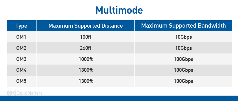
In contrast, multimode cables can only manage much shorter runs of a single cable before amplification is necessary. Legacy OM1 cables are limited to just 100ft, while OM2 provides a higher quality connection and can stretch to 260ft. Their bandwidth is relatively comparable to single mode cables, delivering between 1Gbps and 10 Gbps depending on cable length.

OM3 multimode fiber optic cables can manage longer cable runs at up to 1,000ft, while OM4 and OM5 are capable of 1,300ft cable runs at up to 10 Gbps. All three are also capable of transmitting at a much higher bandwidth: up to 100 Gbps in some cases. However, offering such throughput requires a shorter cable run, with even the most capable OM4 and OM5 cables limited to just 500ft at the maximum bandwidth.

OM1 and OM2 multimode cables can, in some cases, be driven by LED light rather than lasers, which limits their range and performance, as well as their cost. However, OM2 cables are also available with laser optimizations which improve their range and available bandwidth.

To help differentiate between all of these similar, but quite distinct cable types, they are usually given a unique color band. OM1 multimode fiber cables are given orange or grey outer jackets. OM2 cables are orange, while OM3 are often given a cyan or aqua jacket. OM4 cables are given a purple or aqua outer jacket, while OM5 cables are typically lime green.

Both OS1 and OS2 single mode cables are given yellow jackets, which helps them stand out from their multimode contemporaries.

The final difference in the single mode vs. multimode fiber debate is cost. OS1 and OS2 single mode cables tend to be the most expensive, while multimode cables as a whole are cheaper. However, the pricing difference there is more distinct, with OM5 cables getting close to OS2 cable pricing, while OM1 is far more affordable.

Is Multimode Better?

In the single mode vs. multimode fiber debate, there is not one cable that’s the best, but there are some that are better suited to certain situations.

If you need to run fiber optic cable over a vast distance, there’s no argument that single mode OS2 fiber cables are by far the best tool for the job. But if you’re looking to run shorter cables that are just a few hundred feet in length, multimode cables have the potential to not only offer the same ultra-high bandwidth over shorter distances but do so for cheaper, too.

It’s important not to lump all multimode fiber cables together, though, as there are some stark differences between OM1 and OM5 cables, and subtler, but still present differences between the other multimode cable types. Only OM3, OM4, and OM5 cables can offer the same 40Gbps, and 100Gbps bandwidth as OS2 cables, even if it’s over much shorter distances.

With that in mind, it can often be better to use OM4 or OM5 cables instead of OS1 cables when running shorter cable lengths in indoor locations, if given the choice. In that case, multimode fiber cables could be considered “better”. However, there is no replacing the bandwidth and signal robustness of the OS2 single mode fiber optic cable type.

Choosing the Right Fiber Optic Cable

The main consideration when choosing a fiber optic cable is deciding which type you opt for. Single mode vs. multimode fiber cable is a debate you can answer by considering the cable length(s) required as well as the necessary bandwidth. If you are happy with a maximum of 10Gbps bandwidth at lengths under two miles, then you have the choice of OS1 or OM1 and OM2 fiber optic cables. For greater bandwidth over shorter distances, OM3, OM4, and OM5 are valid options, and will likely give you the most cost-effective solution to your networking problem.

If you’re looking for multiple miles of fiber optic cabling, or simply want the most robust networking solutions, then OS2 single mode fiber optic cables are probably your best bet.

That’s not all you should consider, though. There are single mode and multimode cables that come with different jacket ratings for running through walls, or between multiple floors. If you don’t need anything special, look for fiber cables with a standard Optical Fiber Non-conductive riser (OFNR) rating, which should work fine in most instances, including when transiting between floors.

For improved fire protection, plenum-rated fiber optic cables will come with a Low Smoke Zero Halogen (LSZH) jacket type, which means that even if it were to set fire, it would give off very little smoke or halogenic compounds. There are also both simplex and duplex fiber patch cables which have single or dual connectors on each end. If you’re unsure which you need, you can always just buy a duplex cable and use one of the connectors if that’s all you ultimately need.

You should also consider what type of connector your fiber optic cable needs. Unlike copper twisted pair patch cables which almost universally come with RJ45 plugs at the end, fiber optic patch cables can come with a range of headers. There are LC connectors which are the most common and are somewhat smaller than their comparable sibling, SC connectors, and are most commonly found on single mode fiber optic cables.

SC connectors are an older, larger design, but are otherwise comparable and have a locking mechanism, which can make them sturdier. That extra size does make them harder to fit in large numbers in data centers and patch panel cabinets, but they are cheaper and have a more established design.

Less commonly you’ll also find ST fiber optic connectors, which are a similar size to SC connectors but have a twist-bayonet-style mechanism. There’s also the MTP connector which is typically used in data centers and advanced home networks.

For more tips on choosing the right fiber optic cable for you, check out our complete guide to fiber optic cabling.

EthernetNetworkingFiber OpticCat6

Linux File System Table (/etc/fstab file) Explained

In this guide, we will learn what is fstab in Linux, and what is the usage of fstab file, the structure of /etc/fstab file and finally how to debug fstab issues. At the end, we will also discuss a brief introduction to mtab file, its usage and how mtab differs from fstab.

What is fstab?

As a server administrator or Linux desktop user or anyone who is new to Linux, understanding about /etc/fstab file in Linux and how to debug fstab issues are very important.

Fstab is a file system table used by the kernel during boot time to mount the file system. To put it in simple terms, you will create one or more partitions on your hard drive and you will make an entry for each partition in fstab which will be read by the kernel during boot time and the file system will be automatically mounted.

By default, any partitions you create during the OS installation will be automatically added to the fstab file. Let’s dive in and see how fstab is structured and how to use fstab.

NOTE : Before editing the fstab file, it is best practice to take a backup of the file. If in case something is messed up you can revert the backup copy.

Structure of /etc/fstab file

Fstab is located in the /etc/ directory and owned by the root user. So you should edit the file using sudo privilege or as the root user.

Display the fstab file by running the following command to understand its structure.

$ cat /etc/fstab
$ cat /etc/fstab | grep -i -v "^#" | column -t # Skip comments and format
Contents of fstab file

Fstab file consists of six columns (sections).

  1. File system – Block device which is partitioned and created a file system on it.
  2. Mount Point – Where the file system is mounted in your system.
  3. Type – File system type (Ext4, Ext3, swap, Xfs, etc.)
  4. Options – This decides what mount parameters to be considered when mounting the file system
  5. Dump – This is for the backup purposes used by the dump utility. Setting it to zero means disabling the backup and one means enabling the backup to a given device/medium.
  6. Pass – File system check at boot time by the fsck utility. Zero will disable the file system check and for the root file system it should be set to 1 and for other partitions, it should be set to 2.

Each filesystem is described on a separate line. Fields on each line are separated by tabs or spaces.

Let’s see about these six parameters in detail.

1. File System

In the first column of fstab, you need to point to which partition you are going to mount. Either you can use a block device name like /dev/sda* or use the UUID.

When you create a file system on top of any partitioned drive using the mkfs command there will be a UUID created for that particular partition.

Let’s say you created a new partition and it is sdb1. In this case, your fstab will be as follows.

/dev/sdb1 /home ext4 defaults 0 0
Mount using names
Mount using names

To get the block id for any file system run the following command.

$ blkid                # Print info about all fs.
$ blkid /dev/sdb1      # Print info about given fs alone.

Now using this block id you can mount the file system as shown in the below image.

Mount using UUID
Mount using UUID

2. Mount Point

In the second column, you have to specify the mount point directory. Mount point refers to the directory in the file system where your partitioned drive will be mounted.

As you see in the below image, each partition is mounted under a different directory. For example, the partition /dev/sdb1 is dedicated to the home directory and mounted under /home.

Mount point
Mount point

Let’s say you created a new partition with 100GB size and with EXT4 as partition type. The fstab entry will be as follows. Here /mnt/data1 is the mount point.

UUID=xxxx-xxx-xxx /mnt/data1/ ext4 defaults 0 0

Or

/dev/sdb2 /mnt/data1/ ext4 defaults 0 0

3. Filesystem Type

Here you will mention the file system type(EXT2, EXT3, EXT4, XFS, VFAT, SWAP, etc.). If you want to know the file system type for a block device, use blkid or lsblk command.

$ lsblk -f /dev/sdb1
NAME FSTYPE LABEL UUID                                 MOUNTPOINT
sdb1 ext4         365c64d7-4d65-4cdf-8ce1-0def8bb41997 /home
$ blkid /dev/sdb1
/dev/sdb1: UUID="365c64d7-4d65-4cdf-8ce1-0def8bb41997" BLOCK_SIZE="4096" TYPE="ext4" PARTUUID="8f174339-01"
Filesystem type
Filesystem type

4. Mount Options

This is an important column where you will pass mount options for the file system. There are a lot of mount options that can be used. For normal usage using the default option is enough. The option default points to the combination of seven (rwsuiddevexecautonouser, and async) options.

Let’s see what the default option does.

  • rw – This tells the file system to be mounted in read-write mode. When an error occurs you can make the file system to be mounted in read-only mode by using the option errors=remount-ro.
  • suid – Any operation related to suid and sgid will be allowed through this option.
  • dev – It will interpret character and block devices on the file system. If you do not wish to interpret characters and block devices you can use nodev option explicitly.
  • exec – From the file system you can execute the binaries by setting the exec option. Opposite to this, you can use the noexec option to not execute binaries from the file system.
  • auto – This option is responsible for auto mounting the file system during the boot time or whenever you run the mount -a command from the terminal. Opposite to this, there is noauto option that will only allow to mount the file system individually.
  • nouser – Only a superuser can mount the file system. You can also use “user” and “users” options which can set the ordinary user to mount and unmount the file system.
  • async – All the IO operations should be done asynchronously. If you use the option “sync” the IO operation will be done synchronously.

Depending upon the requirement you may need to use different options. If you have any existing production server in your environment, I suggest you take a look at the fstab file which will give you a good idea about what are the mount options used.

Mount options
Mount options

5. Dump

This column is specific for backup purposes. When it is set to 1, the dump utility will take backups. This is an obsolete feature now as it was originally designed to take backups in tapes for older file systems.

It is recommended to set it to zero.

Dump column in fstab

6. Pass

During boot time the fsck utility will do a file system check based on the value we provide in the sixth column. If you set the value to zero or leave it empty, the file system check will be disabled.

The root file system should always be specified to the value 1. For other file systems, you can set the value to 2. Since I am using VM for the demonstration, I have set all the values to zero.

Pass column in fstab

If you made any mistake in the fstab file and when you reboot the machine it will go into emergency mode. In emergency mode, there will be no network interface so you have to debug directly in the console.

Emergency mode
Boot into Emergency mode

You have to type the root password to enter into the emergency mode. Run the following command and scroll slowly to see for error messages. In my case, I intentionally removed the separator (/) in /dev/sdb1.

Fix Boot problems related to Fstab file

In emergency mode, if the file system is mounted in read-only mode then you have to mount in rw mode and edit the fstab file to fix the problem. To remount the file system in rw mode run the following command.

$ mount -o rw,remount /

Now edit the fstab to fix the error and reboot the machine. Now your machine should be able to boot properly.

$ reboot

To avoid the issues during boot time, you can run the mount command after adding the fstab entries.

Take a look at the below image where I have added a new entry for /dev/sdb2. I have not specified the file system type so it will throw me an error when I run the mount command.

Filesystem type error
$ mount -a
mount: /mnt: unknown filesystem type 'defaults'.

What is a Mtab File?

When you run the mount command without passing any arguments it prints the list of mounted file systems.

$ mount

There is also a file called mtab in the /etc/ directory. When you look at /etc/mtab, it will be exactly the same as the output of the mount command.

Let’s see what the man page has to say about the mtab file.

What is mtab file
What is mtab file

The /etc/mtab file is symlinked to mounts in the proc file system. If you run the mount or umount command the result will be updated in mounts.

$ ls -ln /etc/mtab
lrwxrwxrwx 1 0 0 19 Jan 9 17:45 /etc/mtab -> ../proc/self/mounts

To summarize the difference between fstab and mtab, fstab is used to mount the file system during the boot time and mtab is used to display the list of file systems mounted.

If /etc/mtab file is corrupted or deleted by accident, you can regenerate it by using the following command.

$ sudo sh -c 'grep -v rootfs /proc/mounts > /etc/mtab'

Conclusion

In this article we have discussed what is fstab and mtab and how it is important for the system to store and read the partition information during boot time. We also discussed what happens when there is a mistake made in the fstab file.

How to Pass-through PCIe NICs with Proxmox VE on Intel and AMD

Proxmox VE Web GUI Pick NIC To Pass Through

A quick one today is the super-simple tutorial for getting NICs passed through to virtual machines on Promxox VE. Passing-through NICs avoid the hypervisor overhead and also can help with compatibility issues using virtual NICs and some firewall appliances like pfSense and OPNsense. The downside is that unless the NICs support SR-IOV, they most likely will not be shared devices in this configuration.

Step 1: BIOS Setup

The first thing one needs to do is to turn on the IOMMU feature on your system. For this, the CPU and the platform need to support the feature. These days, most platforms will support IOMMU, but some older platforms do not. On Intel platforms, this is called “VT-d”. That stands for Intel Virtualization Technology for Directed I/O (VT-d.)

Enable Intel VT D To Get IOMMU Working

On AMD platforms you will likely see AMD-Vi as the option. Sometimes in different system firmware, you will see IOMMU. These are the options you want to enable.

Of course, since this is Proxmox VE, you will want to ensure your basic virtualization is on as well while you are in the BIOS. Also, since it is going to likely be a main focus for people using this guide, if you are making a firewall/ router on the machine, we usually suggest setting the On AC Power setting to “Always on” or “Last state” so that in the event of a power failure, your network comes up immediately.

Next, we need to determine if we are using GRUB or systemd as the bootloader.

Step 2: Determine if you are Using GRUB or systemd

This is a newer step, but if you install a recent version of Proxmox VE, and are using ZFS as the root (this may expand in the future) you likely are using systemd not GRUB. After installation, use this command to determine which you are using:

efibootmgr -v

If you see something like “File(\EFI\SYSTEMD\SYSTEMD-BOOTX64.EFI)” then you are using systemd, not GRUB.

Another giveaway is when you boot, if you see a blue screen with GRUB and a number of options just before going into the OS, then you are using GRUB. If you see something like this, you are using systemd:

Proxmox VE Systemd Boot Menu

This is important because many older guides are using GRUB, but if you are using systemd, and follow the GRUB instructions, you will not enable IOMMU needed for NIC pass-through.

Step 3a: Enable IOMMU using GRUB

If you have GRUB, and most installations today will, then you will need to edit your configuration file:

nano /etc/default/grub

For Intel CPUs add quiet intel_iommu=on:

GRUB_CMDLINE_LINUX_DEFAULT="quiet intel_iommu=on"

For AMD CPUs add quiet amd_iommu=on:

GRUB_CMDLINE_LINUX_DEFAULT="quiet amd_iommu=on"

Here is a screenshot with the intel line to show you where to put it:

Proxmox VE Nano Grub Quiet Intel Iommu On

Optionally, one can also add IOMMU PT mode. PT mode improves the performance of other PCIe devices in the system when passthrough is being used. This works on Intel and AMD CPUs and is iommu=pt. Here is the AMD version, of what would be added, and we will have an Intel screenshot following:

GRUB_CMDLINE_LINUX_DEFAULT="quiet amd_iommu=on iommu=pt"

Here is the screenshot of where this goes:

Proxmox VE Nano Grub Quiet Intel Iommu On Iommu Pt

Remember to save and exit.

Now we need to update GRUB:

update-grub

Now to go Step 4.

Step 3a: Enable IOMMU using systemd

If in Step 2 you found you were using systemd, then adding bits to GRUB will not work. Instead, here is what to do:

nano /etc/kernel/cmdline

For Intel CPUs add:

quiet intel_iommu=on

For AMD CPUs add:

quiet amd_iommu=on

Here is a screenshot of where to add this using the Intel version:

Proxmox VE Systemd Quiet Intel_iommu=on

Optionally, one can also add IOMMU PT mode. This works on Intel and AMD CPUs and is iommu=pt. Here is the AMD version, of what would be added, and we will have an Intel screenshot following:

quiet amd_iommu=on iommu=pt

Here is the Intel screenshot:

Proxmox VE Systemd Quiet Intel_iommu=on Iommu=pt

Now we need to refresh our boot tool.

proxmox-boot-tool refresh

Now go to Step 4.

Step 4: Add Modules

Many will immediately reboot after the above is done, and it is probably a good practice. Usually, I like to add modules just to save time. If you are more conservative, reboot, then do this step. Next, you will want to add modules by editing:

nano /etc/modules

In that file you will want to add:

vfio
vfio_iommu_type1
vfio_pci
vfio_virqfd

Here is what it should look like:

Proxmox VE NIC Pass Through Etc Modules Additions
Proxmox VE NIC Pass-Through Etc Modules Additions

Next, you can reboot.

Step 5: Reboot

This is a big enough change that you will want to reboot next. With PVE, a tip we have is to reboot often when setting up the base system. You do not want to spend hours building a configuration then find out it does not boot and you are unsure of why.

We will quickly note that we condensed the above a bit for more modern systems. If something fails in the verify step below, you may want to reboot before adding modules instead, and also not turn on PT mode before rebooting.

Step 7: Verify Everything is Working

This is the command you will want to use:

dmesg | grep -e DMAR -e IOMMU

Depending on the system, which options you have, and so forth, a lot of the output is going to change here. What you are looking for is the line highlighted in the screenshot DMAR: IOMMU enabled:

Proxmox VE IOMMU Enabled

If you have that, you are likely in good shape.

Step 7: Configure Proxmox VE VMs to Use NICs

For this, we are using a little box very similar to the Inexpensive 4x 2.5GbE Fanless Router Firewall Box Review. It is essentially the same, just a different version of that box. One of the nice features is that each NIC is its own i225-V and we can pass through each individual NIC to a VM. Here is a screenshot from an upcoming video we have:

Proxmox VE Web GUI Pick NIC To Pass Through
Proxmox VE Web GUI Pick NIC To Pass-Through

In the old days, adding a pass-through NIC to a VM was done via CLI editing. Now, Proxmox pulls the PCIe device ID and then also the device vendor and name. This makes it very easy to pick NICs in a system. One point that is nice about many of the onboard NICs is that the physical ordering as the NICs are labeled on the system should mean that we have sequential MAC addresses and PCIe IDs. In the above 0000:01:00.0 is the first NIC (ETH0). The device 0000:02:00.0 is the second, and so forth.

Hunsn 4 Port 2.5GbE I225 Intel J4125 Firewall Box NIC Ports

At this point, you are already done. You can see we have this working on both OPNsense and pfSense and the process is very similar. The nice thing is that by doing this, pfSense/ OPNsense have direct access to the NICs instead of using a virtualized NIC device.

A Few Notes on IOMMU with pfSense and OPNsense

After these NICs are assigned there are a few key considerations that are important to keep in mind:

  • Using a pass-through NIC will make it so the VM will not live migrate. If a VM expects a physical NIC at a PCIe location, and it does not get it, that will be an issue.
  • Conceptually, there is a more advanced feature called SR-IOV that allows you to pass through a NIC to multiple devices. For lower-end i210 and i225-V NICs that we commonly see in pfSense and OPNsense appliances, you will be conceptually dedicating the NIC to the VM. That means, another VM cannot use the NIC. Here is an example where we have the pfSense VM (600) using a NIC that is also assigned to the OPNsense NIC. We get an error trying to start OPNsense. The Proxmox VE GUI will allow you to configure pass-through on both VMs if they are off, but only one can be on and active with the dedicated NIC at a time.
Proxmox VE Web GUI NIC Being Assigned To A Second VM
Proxmox VE Web GUI NIC Being Assigned To A Second VM for OPNsense when it is already assigned to pfSense
  • Older hardware may not have IOMMU capabilities. Newer hardware has both IOMMU and ACS, so most newer platforms make it easy to separate PCIe devices and dedicate them to VMs. On older hardware, sometimes how PCIe devices are grouped causes issues if you want to, as in this example, pass-through NICs separately to different VMs.
  • You can utilize both virtual NICs on bridges along with dedicated pass-through NICs in the same VM.
  • At 1GbE speeds, pass-through is not as big of a difference compared to using virtualized NICs. At 25GbE/ 100GbE speeds, it becomes a very large difference.
  • When we discuss DPUs, one of the key differences is that the DPU can handle features like bridging virtual network ports to physical high-speed ports and that happens all on the DPU rather than the host CPU.
  • This is an area where it takes longer to setup than a bare-metal installation, and it adds complexity to a pfSense or OPNsense installation. The benefit one gets is that doing things like reboots is usually much faster in the virtual machine. One can also snapshot the pfSense or OPNsense image in the event one makes a breaking change.
  • We suggest having at least one more NIC in the system for Proxmox VE management and other VM features. If one uses pass-through for all NICs to firewall VMs, then there will not be a system NIC.

How To Create Proxmox Containers From Proxmox Web UI Dashboard

Create And Manage Linux Containers From Proxmox VE Web Dashboard

In this tutorial, we will discuss a brief overview about Linux containers and its use cases. Then we will move on to see how to list available container templates from Proxmox web dashboard, download a container template and finally create Proxmox containers using the downloaded container template from Proxmox dashboard.

If you haven’t installed Proxmox VE yet, refer the following guides.

What Is A Linux Container?

Linux Container (shortly LXC) is an OS-level virtualization method for running multiple isolated applications sharing an underlying Linux kernel. To put this in other words, Containers will use the same kernel of host system that they run on.

A container consists of one or more processes (generally running with reduced privileges) having shared visibility into kernel objects and a common share of host resources.

Shared visibility into kernel objects is governed by namespaces, which prevent processes in one container from interacting with kernel objects, such as files or processes, in an other container.

Resource allocation is governed by cgroups (control groups), provided by the kernel to limit and prioritize resource usage. An LXC container is a set of processes sharing the same collection of namespaces and cgroups.

Containers are very useful to develop, deploy, and test modern distributed apps and microservices that can operate in isolated execution environments on same host systems.

Containers are in high demand because they are lightweight alternatives to fully virtualized machines (VMs). The operating and running costs of containers are very low when compared to VMs.

Create Proxmox Containers From Proxmox Web Dashboard

Proxmox uses Linux Containers (LXC) as its underlying container technology.

We can create and containers from Proxmox VE graphical web user interface (GUI) or from commandline using Proxmox Container Toolkit (pct).

In this tutorial, we will see how to create and manage Proxmox containers from Proxmox web dashboard.

Step 1 – Login To Proxmox Web User Interface

Open the web browser and navigate to https://proxmox-IP-address:8006/ URL. You will be pleased with the Proxmox login page. Enter the username (root) and its password.

Login To Proxmox Web Dashboard

Step 2 – Download Container Images

Container images (also known as templates, or appliances) is a tar archive that is bundled with everything to run a container.

Proxmox provides various templates for popular Linux distributions. As of writing this guide, you can download the Container templates for the following Linux distributions from Proxmox VE official repositories.

  • Alpine Linux
  • Arch Linux
  • CentOS / CentOS Stream / AlmaLinux / Rocky Linux
  • Debian
  • Devuan
  • Fedora
  • Gentoo
  • openSUSE
  • Ubuntu

You can also download various ready-made appliances from Turnkey Linux website.

Turnkey Linux is an open source project that developing a free virtual appliance library that features the very best server-oriented open source software. Each virtual appliance is optimized for ease of use and can be deployed in just a few minutes on bare metal, a virtual machine and in the cloud.

For the purpose of this guide, i am going to use Debian 11 standard template.

Click on the small arrow button besides your Proxmox host name to expand it. And click on the storage named ‘local‘. You will see the following screen.

Click On Storage 'local' On Proxmox  System
Click On Storage ‘local’ On Proxmox System

Click on ‘CT Templates’ option and then click ‘templates’ button.

Click On CT Templates Option

You can also click ‘Upload’ button to upload an already downloaded template or choose ‘Download from URL’ button to download the template from a specific URL. I don’t have any templates on my local disk, so I chose ‘Templates’ button.

Choose the Container template of your choice and hit Download button.

Download Debian Container Template

Now the selected the template will be downloaded and saved on /var/lib/vz/template/cache/ directory in your Proxmox host.

Once the template is downloaded, click the close button.

Debian Template Downloaded

You will now see the list of downloaded templates under ‘CT Templates’ section.

Available Container Templates In Proxmox

Now it is time to create the containers using a downloaded template.

Step 3 – Create Proxmox Container

Right click on the Proxmox node and click “Create CT“. In my case, pvedebian is the name of my Proxmox host.

Create Proxmox Container
Create New Proxmox Container

Enter the name of the container and password for the ‘root’ user. You should not use underscore or space or any special characters for the hostname. Click Next to continue.

Enter Container Hostname And Root Password

Choose the Container template from the ‘Template’ drop-down box and click Next.

Choose Container Template

Enter the disk size for the new container and click Next.

Enter Disk Size For Container

Choose the number of cores and click Next.

Enter Number Of Cores For Container

Enter the RAM size for your Container and click Next.

Enter RAM Size For Container

Enter the IP address and gateway for your container and click Next. Here, the gateway is optional. You can can enter gateway if you want to let the Container to talk to other Containers in the network.

Also, keep in mind that the gateway must be your network bridge’s (vmbr0) IP address and the IP address of the Container should be within the same subnet. For instance, if the IP address of the network bridge is 192.168.1.101, the IP address of the Container should be 192.168.1.x/24. Also you must mention the subnet mask along with the IP address (E.g. 192.168.1.15/24) as well.

Enter IP Address And Gateway For Container

Enter the public DNS server (E.g. 8.8.8.8) if you want to let your container to connect to Internet. Make sure you have typed the DNS in the correct field.

Enter DNS Server IP For Container

Review the settings/options and if you’re OK with it, click Finish button to create the Proxmox Container.

Review Container Settings

Upon successful container creation, you will the ‘TASK OK’ message in the output.

Proxmox Container Is Created Successfully

Close the dialog box and the newly created Proxmox container is listed under your Proxmox node on the left pane.

In the following screenshot, you see the container named ‘debian11ct’ with container ID ‘100’ under ‘pvedebian’ node.

Click on the Container to view the summary of it.

Container Summary
Container Summary

In the Summary section, you can view the Container’s uptime, cpu usage, memory usage, network traffic, and disk I/O etc.

You can also configure or change the various parameters (E.g. Access Console, Network, DNS, Firewall, Snapshot, Backup etc.) from the center pane.

Configure Container Parameters

Step 4 – Start Containers

To start a Container, just click on its name and then click ‘Start’ button on the top right corner.

Start A Proxmox Container

Step 5 – Access Console Of Containers

To access the console screen of a running Container, click the ‘Console’ action button on the top right corner.

Access Proxmox Console

The console of the running Container will open in a separate browser window. Enter the user name (i.e. root) and its password to login to the Container’s console.

Proxmox Container Console

Even if you close this browser window, the Container remains running in the background.

Did you notice the output of uname command in the above screenshot? It shows the same Kernel version of the Proxmox host, because Containers user the same underlying Kernel of the Proxmox hosts.

Step 6 – Shutdown/Reboot/Stop Containers

You can shutdown or reboot or pause/resume a running container using the respective action buttons on the top.

Shutdown, Reboot, Stop Container

Step 7 – Clone Containers

Shutdown the Container if it is running. Click on the ‘More’ drop-down action button on the top and then choose ‘Clone’ option to clone the Container.

Clone Container
Clone Container

Enter the name to the clone, choose the target storage location. Leave as is if you want to save it in the default location. Click Clone button to start cloning.

Enter Cloned Container Details

Step 8 – Remove Containers

First, make sure the container is powered off. Click on the ‘More’ drop-down button and choose ‘Remove’ option to delete the Container.

Remove Container
Remove Container

Conclusion

In this comprehensive guide, we have discussed how to create Proxmox containers from Proxmox Web user interface. We also looked at how to do basic container management actions such as starting, stopping, deleting and cloning Containers.

Reverting Thin-LVM to “old” Behavior of /var/lib/vz (Proxmox 4.2 and later)

If you installed Proxmox 4.2 (or later), you see yourself confronted with a changed layout of your data. There is no mounted /var/lib/vz LVM volume anymore, instead you find a thin-provisioned volume. This is technically the right choice, but one sometimes want to get the old behavior back, which is described here. This section describes the steps to revert to the “old” layout on a freshly installed Proxmox 4.2:

  • After the Installation your storage configuration in /etc/pve/storage.cfg will look like this:
dir: local
        path /var/lib/vz
        content iso,vztmpl,backup

lvmthin: local-lvm
        thinpool data
        vgname pve
        content rootdir,images
  • You can delete the thin-volume via GUI or manually and have to set the local directory to store images and container aswell. You should have such a config in the end:
dir: local
        path /var/lib/vz
        maxfiles 0
        content backup,iso,vztmpl,rootdir,images
  • Now you need to recreate /var/lib/vz
root@pve-42 ~ > lvs
  LV   VG   Attr       LSize  Pool Origin Data%  Meta%  Move Log Cpy%Sync Convert
  data pve  twi-a-tz-- 16.38g             0.00   0.49
  root pve  -wi-ao----  7.75g
  swap pve  -wi-ao----  3.88g

root@pve-42 ~ > lvremove pve/data
Do you really want to remove active logical volume data? [y/n]: y
  Logical volume "data" successfully removed

root@pve-42 ~ > lvcreate --name data -l +100%FREE pve
  Logical volume "data" created.

root@pve-42 ~ > mkfs.ext4 /dev/pve/data
mke2fs 1.42.12 (29-Aug-2014)
Discarding device blocks: done
Creating filesystem with 5307392 4k blocks and 1327104 inodes
Filesystem UUID: 310d346a-de4e-48ae-83d0-4119088af2e3
Superblock backups stored on blocks:
        32768, 98304, 163840, 229376, 294912, 819200, 884736, 1605632, 2654208,
        4096000

Allocating group tables: done
Writing inode tables: done
Creating journal (32768 blocks): done
Writing superblocks and filesystem accounting information: done
  • Then add the new volume in your /etc/fstab:
/dev/pve/data /var/lib/vz ext4 defaults 0 1
  • Restart to check if everything survives a reboot.

You should end up with a working “old-style” configuration where you “see” your files as it was before Proxmox 4.2

Enable Proxmox No-subscription Repository

You don’t need a license key to use the Proxmox No-subscription repository. It is suitable for home labs users, testing purpose and non-production use.

To enable Proxmox No-subscription repository, edit /etc/apt/sources.list file:

# nano /etc/apt/sources.list

And add the following lines:

deb http://ftp.debian.org/debian bullseye main contrib

deb http://ftp.debian.org/debian bullseye-updates main contrib

# security updates
deb http://security.debian.org bullseye-security main contrib

# PVE pve-no-subscription repository provided by proxmox.com,
# NOT recommended for production use
deb http://download.proxmox.com/debian/pve bullseye pve-no-subscription

Finally, update the repository list:

$ sudo apt update

$ apt full-upgrade

Samba & Bonjour with Avahi

Okay, so you have a shiny new Linux box, and it’s running Samba, all nice and configured to share your files.  You have a Mac, and you want to use it with your nifty new Windows shares.  You can connect with Command-K in the finder, but it doesn’t show up in Finder under the Shared section.

You need Avahi.

I won’t bother going into the details of configuring Samba.  If you’ve not gotten that far, there are some pretty good resources out on the ‘net that will tell you how.  Where interacting with Bonjour is concerned, however, most of the references I found were flat wrong with modern OS X and Samba.

To make this work, the steps are simple (I’m running Ubuntu 12.04, so you may have to adjust accordingly for your Linux distro of choice).  The first step is to install Avahi:

root@core:/# apt-get install avahi-daemon avahi-utils

When this command completes, you’ll essentially have Bonjour running on your Linux box.  This has a number of advantages, most notably that you can now log into the thing by hostname (eg. core.local for my machine) without having to configure DNS.  But it still won’t allow you to browse shares in Finder; for that, you need a bit of configuration.

And so we move to step 2: create a file in /etc/avahi/services called smb.service, and place the following content in it:

<?xml version="1.0" standalone='no'?>
<!DOCTYPE service-group SYSTEM "avahi-service.dtd">
<service-group>
 <name replace-wildcards="yes">%h</name>
 <service>
   <type>_smb._tcp</type>
   <port>445</port>
 </service>
 <service>
   <type>_device-info._tcp</type>
   <port>0</port>
   <txt-record>model=RackMac</txt-record>
 </service>
</service-group>

Upon saving it, your new Linux box will happily appear in the Finder sidebar, and should all work.  You don’t even need to restart Avahi; it’ll pick up the new service file automagically.

There are other references out there for how to do this, but they all use port 139 – which doesn’t work.  I haven’t a clue when Microsoft changed the port number, but whatever; I don’t really care.  I have finder browsing goodness, so I’m happy.

How to Check Open Ports in Linux?

Which ports are occupied by which service? How many open ports are there? Learn to scan for open ports on your Linux system or any remote system.Table of Contents

  1. Method 1: Checking open ports in the currently logged in Linux system using lsof command
  2. Method 2: Checking ports on any remote Linux server using the netcat command
  3. Conclusion

Whether you are using Linux as a server or desktop, knowing open ports or ports in use can be helpful in a variety of situations.

For example, if you are running an Apache or Ngnix based web server, the port in use should be 80 or 443. Checking the ports will confirm that. Similarly, you can check which port is being used by SMTP or SSH or some other services. Knowing which ports are in use can be helpful while allocating the ports to a new service.

You may also check if there are open ports for intrusion detection.

There are various ways for checking ports in Linux. I’ll share two of my favorite methods in this quick tip.

Method 1: Checking open ports in the currently logged in Linux system using lsof command

If you are logged into a system, either directly or via SSH, you can use the lsof command to check its ports.

sudo lsof -i -P -n

This lsof command is used to find the files and processes used by a user. The options user here are:

  • -i: If no IP address is specified, this option selects the listing of all network files
  • -P: inhibits the conversion of port numbers to port names for network files
  • -n: inhibits the conversion of network numbers to host names for network files
Checking open ports in Linux

But, this also shows us a lot of extra ports that the computer does not actually listen to.

You can just pipe this output to the grep command and match the pattern “LISTEN”, like this:

sudo lsof -i -P -n | grep LISTEN

This will only show the ports that our computer is actively listening to and also which service is using said open port.

Method 2: Checking ports on any remote Linux server using the netcat command

nc (Netcat) is a command line utility that read and writes data between computers over network using the TCP and UDP protocols.

Given below is the syntax for nc command:

nc [options] host port

This utility has a nifty -z flag. When used, it will make nc scan for listening daemons without actually sending any data to the port.

Combine this with the -v flag, enabling verbosity, you can get a detailed output.

Below is the command you can use to scan for open ports using the nc command:

nc -z -v <IP-ADDRESS> 1-65535 2>&1 | grep -v 'Connection refused'

Replace IP-ADDRESS with the IP address of the Linux system you are checking the ports for.

As for why I selected values 1 to 65535, that is because the port range starts from 1 and ends at 65535.

Finally, pipe the output to the grep command. Using the -v option, it excludes any line that has “Connection refused” as a matched pattern.

This will show all the ports that are open on the computer which are accessible by another machine on the network.

Conclusion

Of the two methods, I prefer the lsof command. It’s quicker than nc command. However, you need to be logged into the system and have sudo access for that. In other words, lsof is more suitable a choice if you are managing a system.

The nc command has the flexibility of scanning ports without being logged in.

Both commands can be used for checking open ports in Linux based on the scenario you are in. Enjoy.TipsSHARE